the TVR SEAC pages
written and photographed by Hamish Cubitt
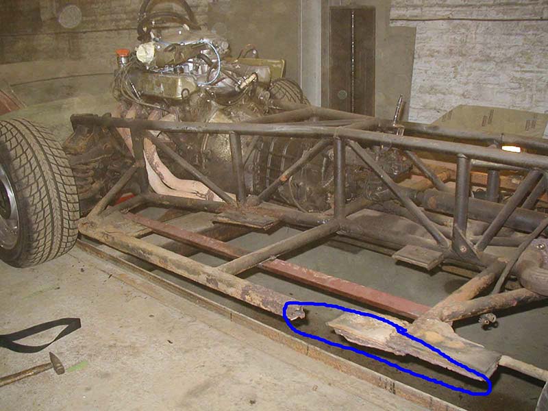
When I purchased my 400SE in September 2001 the car was almost 11 years old. It was built in 1989 and first registered on 1 January 1990, and had done about 65,000 miles.I was aware that the chassis had been repaired, and expected it to last for a couple of years before needing further attention. Everything was covered in underseal.
When I checked the car over prior to its MOT coming due in September 2005 I found more corrosion in the nearside outrigger square tube. Scraping off the underseal and exploring for sound metal revealed that some tube renewal was required. The chassis was also rusty in a number of areas and had original sound powder coating in many areas.
At this point I decided to remove the body to do a proper repair to the nearside outrigger and properly clean and paint the chassis. (On the 400 SE the sills are a part of the body, not separate panels as per 350 series)
The following is the story of what I found and some of the additional work I carried out whilst access was easy.
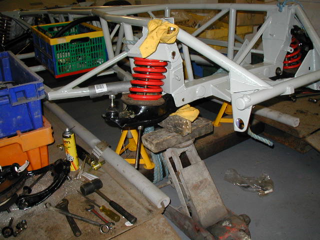
I was fortunate in having long term use of a friends four post lorry hoist to assist in the task. The body was disconnected from the chassis and raised using four tall axle stands to support it with the hoist being lowered with the chassis on it. Two lengths of steel tube were then used to support the body on top of the chassis. These allowed repositioning of the axle stands to the outside of the hoist. The body was then supported on the tubes on the axle stands and the chassis rolled clear.
Full details of items requiring disconnection, the lifting process etc are given later separately
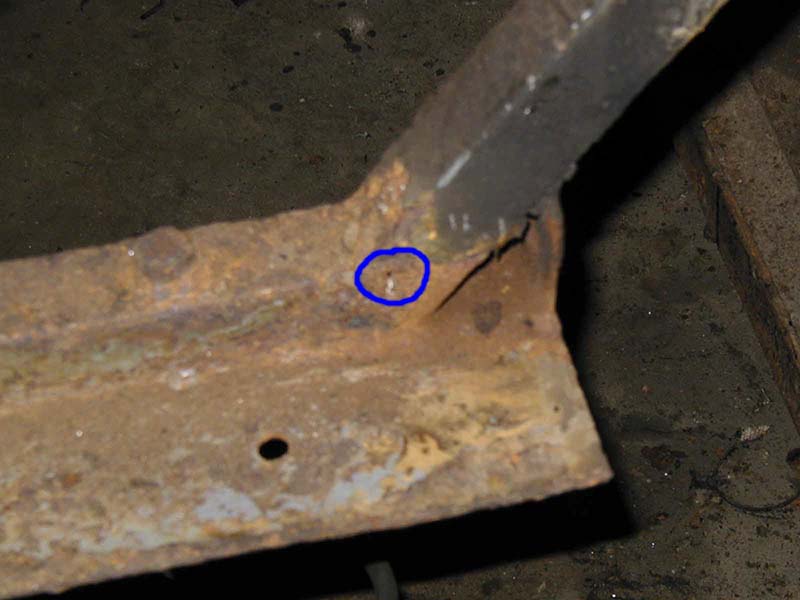
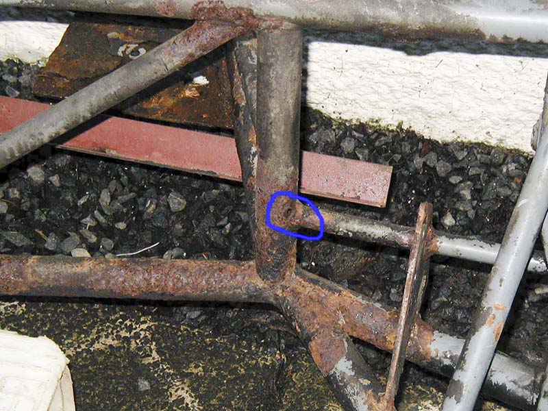
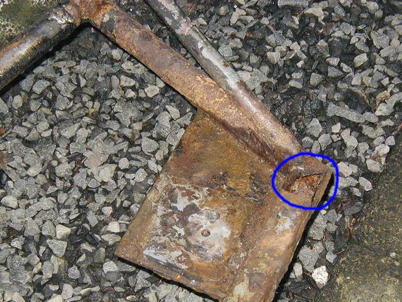
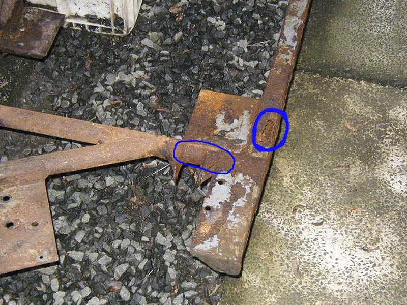
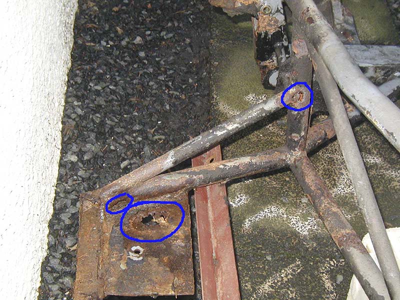
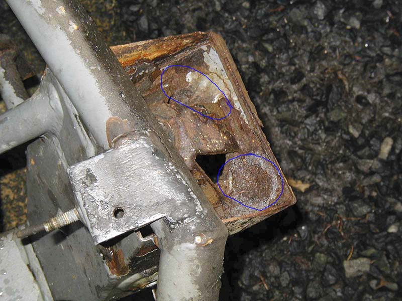
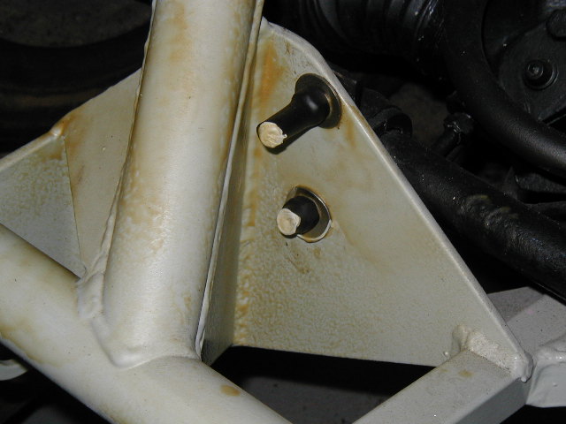
Once the body was removed I was able to properly inspect the chassis. I found much more corrosion than I had expected. About 90% of the chassis was sound with original powder coating intact, or with little corrosion. About a dozen local areas required repair. Defect locations ranged from outriggers (badly corroded), short section of tube in way of the rear radius arm mounting brackets (thin), the square plate seating platforms for the front suspension springs (thin), a number of locations next to body mounting plates (holed), various locations where tubes were locally holed - but sound a few inches away, etc. Some locations would have been impossible to see with the body on e.g. three holes adjacent to weld connections of the top main chassis rail area - to the rear of the engine, on the body side of the tubes.
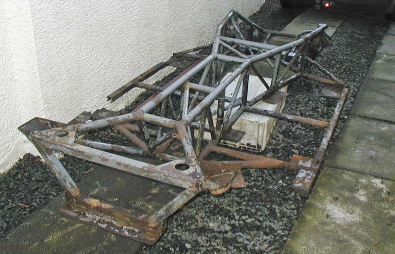
The chassis could have been repaired, but would have required fabrication of a jig, and a fair bit of work. A new chassis was available to order from the factory at an affordable price, and the decision was taken to renew the chassis.
The factory required the old chassis be returned (to ensure a correctly dimensioned chassis was supplied), and about 6 weeks time to fabricate a new chassis. The new chassis also came with the same number as the old one.
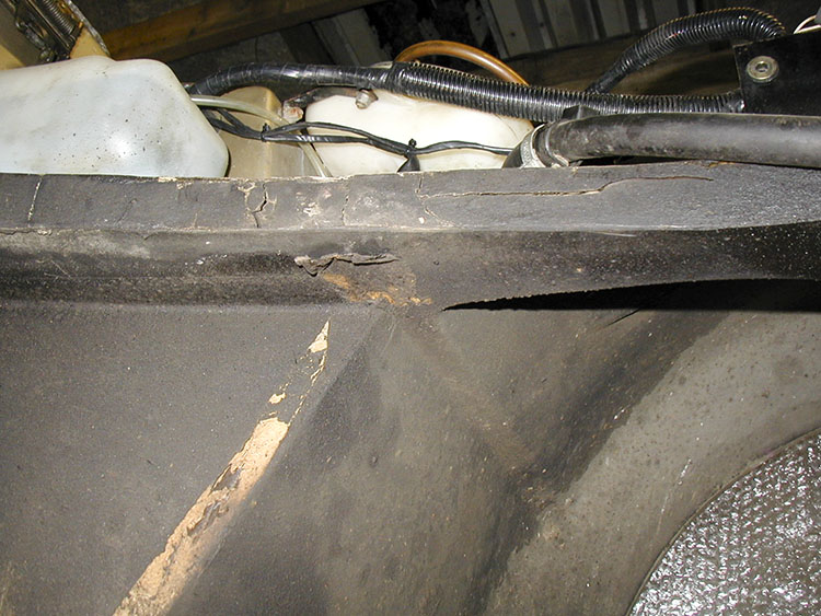
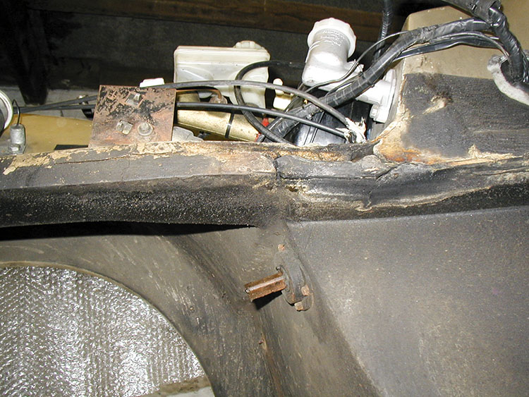
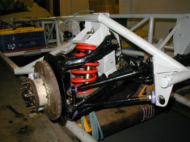
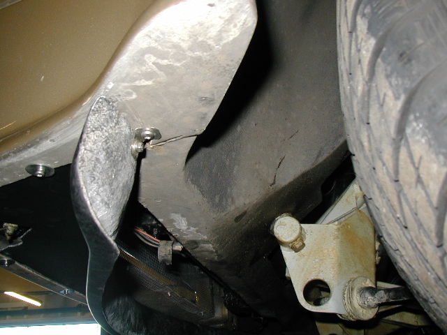
The following photos were taken after removal of the body and after strip down and High pressure washing of the old chassis. They show the general condition and locations where corrosion had occurred.


The body was found to have split where the two parts join near the engine exhaust (a known weakness).
Nearside
Offside
While the new chassis was awaited the following work was done:
Removed parts were cleaned, painted etc.
Suspension parts were given 2 coats of galvafroid (zinc rich paint), and 2 coats of Hammerite - Smoothrite, plus waxoyl in cavities (eg rear hub structure)
The body was cleaned and repairs made to the split areas in the engine bay.
Fuel tanks were only slightly rusty at the seams and were painted and waxoyl coated. I find melting the waxoyl with a hot air gun after application helps to give an even wax coating and helps dry it off a bit for easier handling.
Dashboard veneered panels and door trim strips were sent off for re-veneering
Brakes were overhauled: new , seals, pads, and grooved discs at the rear; and at the front, new pistons, seals, pads, and existing discs sent off to have grooves machined.
A missing bush for the gear selector rod (in the gear lever extension housing) was fabricated and fitted
Spot checks were made to the engine, clutch, crankshaft bearings, rocker area etc and all found in order.
Leaks from shaft oils seals on the engine and gearbox were dealt with.
New suspension bushes fitted (polybushes) to wishbones etc. Rubber seal strips beside the radiator were renewed
Rubber strip flaps in the radiator fan housing were renewed.
Gear lever rubber gaiter was split - renewed
The new chassis was delivered to the local TVR dealer and I collected from there.
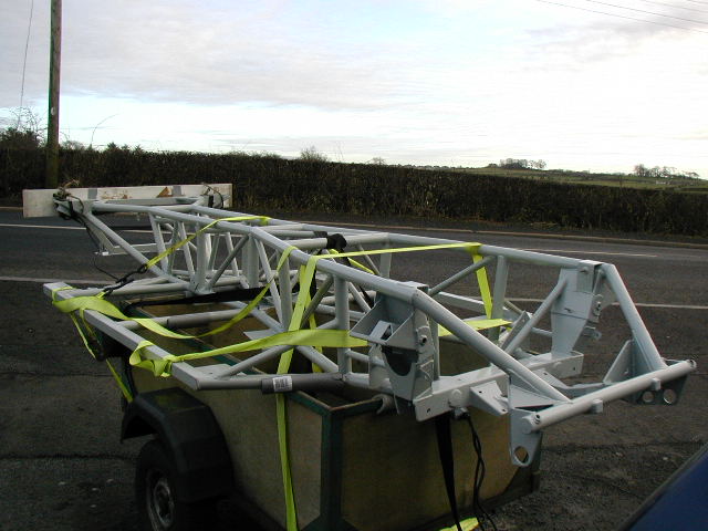
Tubular foam plumbing pipe insulation was used to protect the chassis coating from damage at any contact points.
A few scratches in the powder coating were touched up with Hammerite - smoothrite (a grey mix of black and white colours to match the chassis powder coating)
Some water/mud trap areas on the chassis were filled with mastic (Sikaflex) eg rear shock absorber mounting plates, inboard seat belt mounting brackets on lower main chassis tubes etc.
Waxoyl was applied locally before anything was bolted to the chassis.
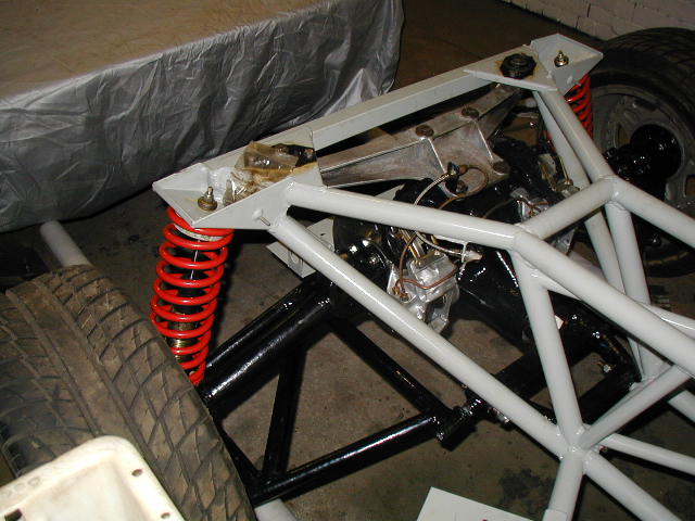
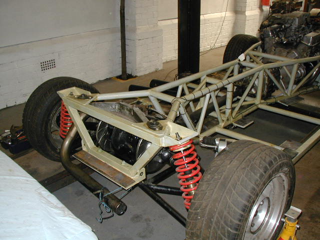
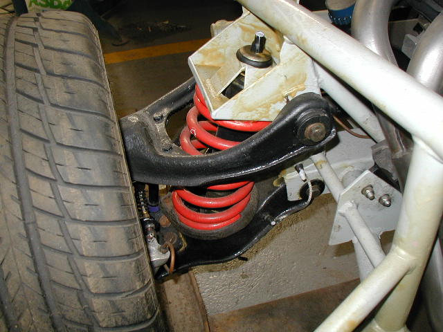
New powder coated suspension springs (standard) and Redline adjustable shock absorbers were fitted.
Brake piping was copper tube material so was re-used. and new stainless braided hoses were fitted.
New fuel hoses were fitted throughout the car.
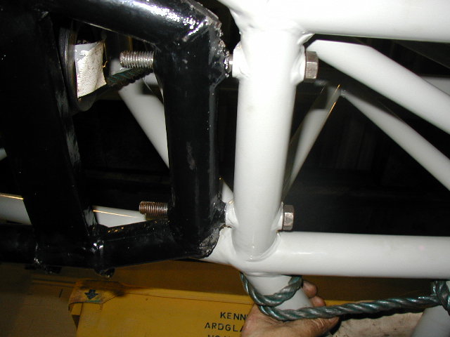
A small problem was experienced when fitting the frame under the differential - the gap in the chassis appeared too small !
Information from the factory was that the chassis had probably slightly sprung when removed from the jig. The differential frame should be bolted at the rear first then levered in to position at the front. Any small difference in the gaps should then be made up with a shim washer.

The front suspension lower wishbone required fabrication of a tool for assembly. A length of screwed rod plus a plate similar to the lower shock absorber mounting plate and some nuts did the job
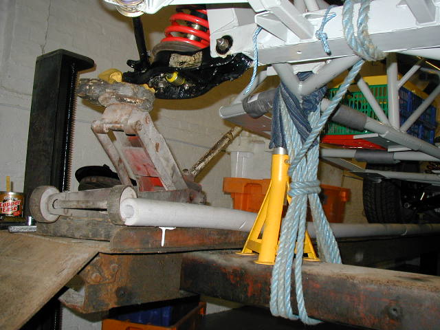
Without the weight of the engine and body it was necessary to tie down the chassis when using a jack placed under the outer end of the wishbone for substitution of the shock absorber instead of the screwed rod.
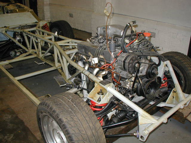
After assembly of suspension parts to the chassis it all looked very good.
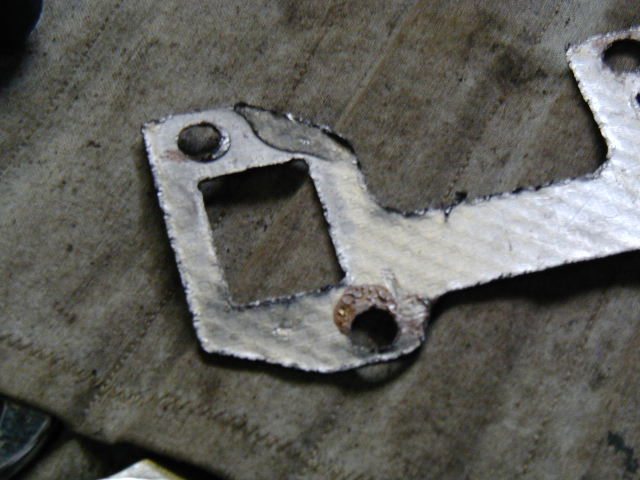
When the new stainless manifolds were offered up to the engine it was evident that there was a very narrow seal in one spot - see gasket impression
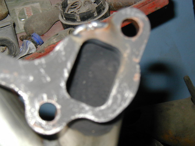
This was resolved by welding on the flange to give a better contact face
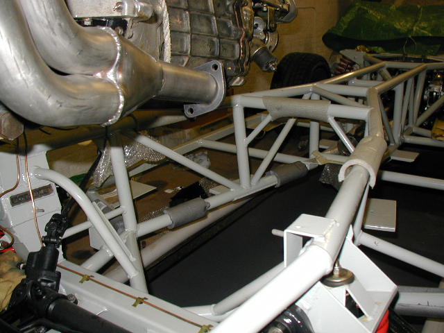
The propeller shaft was sat in the chassis before installing the engine. Once again foam pipe insulation was used to avoid chassis coating damage.
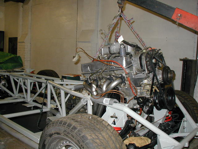
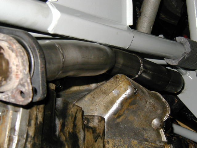
The right hand exhaust manifold was a very tight fit between the clutch housing and the chassis. The exhaust was locally flattened a bit by use of large hammer and squeezing in a
large vice. After the car was on the road again the exhaust was modified by a specialist who added an extra joint and routed the right hand pipe over the bulge in the clutch housing (for the clutch actuating rod)
New earthing braid was fitted at all chassis points.
As I plan to use my car all year round, in all weathers, I was more interested in preservation than concours appearance. Before mounting the body on the chassis the top faces of the chassis were coated in waxoyl.
Fuel tanks were refitted to the body with new stainless steel straps.
The body was fitted to the chassis in the reverse of the procedure used when removing it. The body sits on rubber shims on the chassis. These are of differing thickness. Factory advice for installing the rubber shims at the body/chassis mounting connections was to start at the front and work back, paying attention to door gaps, door alignment etc using appropriate thickness of rubber.
I obtained some nitrile rubber in about 3mm and 6 mm thickness from a local pipe joint manufacturer and cut appropriate sized pieces out. Desired thickness was built up in layers.
The chassis was coated with waxoyl from the underside after assembly was completed.
All exposed bolt threads under the car were capped using heat shrink sleeving with a mastic plug in the end. With the exception of high stress areas (eg. suspension) stainless steel bolts and nuts were used during re-assembly.
When fitting the splitter/Underspoiler under the front I used screws to attach it (rather than pop rivets) so it could be removed easily if the car needed towed.
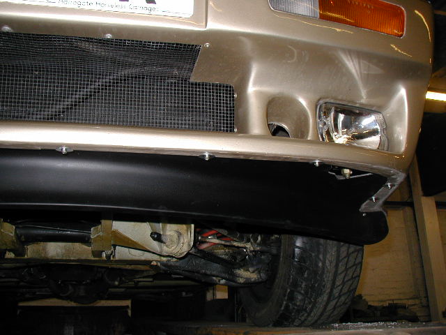
The towing eyes on the chassis do not protrude below the splitter
POINTS OF NOTE AND LESSONS LEARNED
Take lots of photos before you start and as you proceed.
Label all wiring and hose connections - identify which end of the hose goes where.
Bag and label small loose items.
Although I took over 150 photographs during dismantling I still had nothing showing exact routing of some wiring and hose connections. Useful sources of labels are freezer bag tie-tags that you can write on (from Lakeland Ltd or similar source. Small zip fastened bags are useful (write-on bags from local office stationary supplier - my local source was Office World (now Staples)
The only things I think I would do differently another time are: Paint the underside of the body a light colour while the body is off. It would be much brighter to work on after assembly. Take more photos. Be more methodical taking photos e.g. take photos from several directions at regular intervals especially when dismantling wiring and small hoses in engine bay. Powder coat suspension parts.
Removal of Body from Chassis FULL DETAILS
1. GENERAL COMMENTS
CAUTION - the following refers to a specific 1989 built 1990 registered TVR 400 SE with Flapper air flow meter for engine - there may be differences of location or fittings on other cars. All bolts/nuts directly tightening on to fibreglass should be backed up with penny washers in order to spread load. Bolt sizes appear to be mostly metric sizes around the body, but engine and some fittings use A/F sizes. When body is off chassis keep doors closed- they stiffen the body. Basic philosophy - leave engine and running gear on chassis, main wiring harness in body.2. PROCEDURE USED
In this case the car was on a workshop four post hoist (lorry hoist)Disconnections made as listed separately below - item 3.
BODY/CHASSIS DISMOUNTING SEQUENCE
Mark wheel positions on hoist
Support body on 4 tall axle stands located at front of foot wells and base of bulkhead behind seats
Mark positions of axle stands on floor. (spray paint and numbered location)
Lower hoist slowly - check body separating from mounting points
Mark rubber shims/location - different thickness may be used at individual locations
Pass support tubes over top of chassis close to axle stands
Raise body so support tubes take weight off axle stands Re-position axle stands outboard of hoist
Lower hoist so tubes/body land on tall axle stands Roll chassis out from under body
Raise hoist and pick up body (on support tubes) with hoist
Remove axle stands
Fit additional support at rear overhang of body (under boot) and in front of front wheel arches - just enough to take weight of overhanging body and avoid any sagging at ends over time.
Materials:
1 length (7.8 metres) of 76mm outside diameter 3mm wall thickness mild steel tube (cut into 2 pieces) was more than enough to span the lorry hoist used in this case)
4 Tall axle stands
Various wooden blocks
Alternative possible lifting methods for body
- use two post hoist - I understand this is used with the arms lifting body off chassis at locations close to wheel arches (I believe Peninsula Automotive use this method)
- a squad of strong friends prepared to grunt a bit ( I know 8 people is sufficient for a Reliant Scimitar GTE possibly 6 would do for an open TVR) - untried by me!
- jack up a corner at a time and support on blocks - raise a small amount each time (max 1 inch) to avoid twisting body too much.
3. DISCONNECTIONS
Disconnect and remove battery (contact car alarm/immobiliser supplier for procedure to follow when disconnecting battery - if alarm is fitted)INSIDE
Remove seats (Note there may be spacers under the rear of the seats) - four bolts each seatRemove seat belt securing bolts from the side of the transmission tunnel (note spacers underneath on these bolts between body and chassis)
Remove outer seat belt bolts from floor/chassis
Remove gear lever knob
Remove footwell carpets
Remove bolts through floor at outer corner of footwell (1 each side)
Remove rear quarter trim (and speakers)
Disconnect shoulder and reel bolts for seatbelts
Disconnect bolts (2 each side) through floor which secure tubular support for roof and shoulder mounting for seat belt (behind b post)
Disconnect 2 bolts through boot floor securing body to chassis
UNDERNEATH
Disconnect speedometer cable from gearboxRemove/find spacers between body and chassis in way of inner bolts of seat belts - on sides of transmission tunnel (Total 4 pieces)
Disconnect fuel inlet hose to fuel pump and drain fuel tanks
Disconnect swirl pot hoses at left and right fuel tanks and hose at fuel pump
Disconnect small bore hose (vent to LH tank) from top of swirlpot
Remove fuel swirlpot
Remove upper hose between fuel tanks (at top of tanks)
Disconnect fuel return hose from engine to near side fuel tank at in-line connector below nearside fuel tank
Disconnect wiring from fuel pump (note: + and - connections)
Disconnect fuel tank level gauge wiring at sender on offside fuel tank
Disconnect handbrake cable from calipers
Remove exhaust finishing trim through rear body (secured by 1 pinch bolt)
Remove exhaust final bend
Remove exhaust support under boot (2 bolts)
Cut various cable ties securing hoses and wiring
Disconnect earth wire from nearside shock absorber (upper) bracket on chassis. (Check is same on off side)
Disconnect starter solenoid wire (small wire on spade terminal)
Drain cooling water via radiator hose connection
Disconnect 2 bolts securing body to chassis front cross tube (near radiator bottom)
UNDER BONNET / ENGINE BAY
Remove bonnetCut various cable ties
Unbolt oil filter bracket from body
Unbolt oil thermostat from body
Disconnect main starter cable from battery at starter end
Disconnect throttle cable at plenum end
Disconnect bonnet release cable at latch end (if threaded through hoses/wiring on engine) /> Unplug power resistor and air flow meter connections
Remove air flow meter and ducting to plenum (cover over plenum inlet)
Disconnect heater water valve cable at valve
Disconnect fuel pipes to engine (mark which is which)
Disconnect and remove main water pipes between engine and radiator
Disconnect 2 hoses at radiator header tank (mark which is which) and hang over engine Disconnect earth wiring (from front) at resistor block securing bolt
Disconnect wiring from resistor blocks (mark which is which)
Disconnect wiring to horn Disconnect earth connection wire from ignition coil mounting bolt
Disconnect 2 hoses to heater
Disconnect earth strap from rear offside engine lifting bracket
Disconnect 2 earth connections from rear nearside engine lifting bracket
Disconnect wire to oil pressure switch
Disconnect wire to oil pressure transmitter
Disconnect alternator wiring (2 wires)
Disconnect wire to temperature sensor at front of block
Disconnect electrical plug at distributor
Disconnect link wire from offside engine wiring harness at nearside wiring harness (round plug/socket)
Unplug 4 offside fuel injector wiring plugs
Unplug 1 wiring connector at offside of plenum
Unplug 1 wiring connector at ?differential pressure switch? sensor in front (offside, top) of engine
Pull back engine wiring harness (offside) from engine and lay on body
Disconnect 2 hoses to oil cooler from oil thermostat
Disconnect 2 brake pipes from brake master cylinder and bend clear of body
Disconnect 1 brake pipe from pressure limiting valve and bend clear of body
Disconnect clutch hydraulic pipe from clutch master cylinder
Disconnect vacuum hose between plenum and brake servo Strap/cable-tie oil filter to engine (clear of body)
Pull speedometer cable clear of engine
Unplug 4 near side fuel injector plugs (connections under plenum are awkward - home made tools were used to unhook the plug securing wire clips)
Unplug 2 connectors at front of nearside inlet manifold
Pull back near side engine wiring harness and lay on body
Disconnect two bolts securing body to brackets on chassis inboard of wheel arch (near coil on offside and near resistors on near side)
OFFSIDE FRONT WHEEL ARCH
1. Remove wheel2. Mark steering column joint (close to bulkhead) and disconnect
3. Thread 2 fuel pipes out engine bay through inner wing top (note 2 grommets - 1 in upper, 1 in lower body moulding)
4. Remove/cut clips securing fuel pipes to body in wheel arch
5. Refit wheel
BODY/CHASSIS BOLT CONNECTIONS
(note some of these are under carpets or behind trim) 2 abt .. x .. mm @ centre bottom of boot - chassis to rear of diff4 abt .. x .. mm (2 each side) @ base of B post steel tube (to rear of door aperture)
2 abt .. x .. mm (1 each side) @ outboard seat (lap) belt mounting
2 abt .. x .. mm (1 each side) @ inboard seat (lap) belt mounting on vertical side of transmission tunnel
2 abt .. x .. mm (1 each side) @ inner edge of footwells adjacent to gearbox
2 abt .. x .. mm (1 each side) @ front of footwells towards outer edges of floor
2 abt .. x .. mm (1 each side) @ under bonnet - close to wheel arches (near ignition coil and resistors)
2 abt .. x .. mm (1 each side) @ front cross tube near radiator
TIMESCALE
(assuming car raised for work above/beneath with 1 man working mostly alone)Disconnections prior to body removal - about 4 Man days (including time to remove seized nuts/bolts etc)
Removing body - 1/2 day (with 1 or 2 assistants)
Stripping Chassis - about 4 man days (including time to remove seized nuts/bolts etc.)
Acknowledgements
Thanks to following for information and adviceMike Bressington
Steve Heath
Richard Thorpe (RT Racing)
Richard Smith (Dulford Automotive)
Noel Flannery ( V8 Sports and Classics, Drem, East Lothian)
Neil Hyde
Mike Day at TVR Factory
For assistance with repairs, and facilities: Sandy Wallace (Wallace's Garage, Knockentiber, Ayrshire)